Good News : My LiFePO4 DIY ESS is now even more precise !
Saturday, I received my last order: an RC ESC : Electronic Speed Controller for Radio Controlled models
I had this idea from the beginning of my project and wanted to use one of those to deliver the exact amount of power to the DC - input- side of a big -several thousands of Watts - Grid Tie Inverter ; But I gave up the idea because this contoller would have to be able to deal with pretty big current : 100A or more and a big GTI is pricy too, and running it at low power could cause it to be very inefficient ...
But lately this idea came back to me, and this time, I thought: Why not use an ESC on one of the GTIs only, this way this GTI's output would vary from 0W to 220W instead being 0W -OFF- or 220W -ON-, and the ESC would have to deal with only 10A of DC current from the battery pack to the GTI's input (220W / 25V = 8.8V)
So I started to look into a good quality Electronic Speed Controller and found this one right away after reading about it on a RC boat forum in France, somebody was looking for a 24V "beefy" ESC and somebody advised this one right away, saying it was a quality product, that would do the job with no over heating problem ... After a little email exchange with the British maker of those I got the strongest one that can do 40A and is forward only -which is exactly what I need here -
So this is an important step stone of my DIY ESS project here and it took place yesterday, pretty much all day ...
Royal Mail package received from the UK

and here is the nice Electronize ESC

After trying to test it with a potentiometer and realizing that it would not work, and had to digg out and old RC boat and used the remote control to test the Controller

using the receiver unplugging the boat ESC, and plugging in the new ESC

testing with a 12V AGM battery first, a voltmeter and a DC motor

I found the Neutral point using the remote trim, and reading 12.55V on the voltmeter

now pushing the lever forward or backwards the voltage climbed to 13.25 which was the battery's voltage

After this first test, I connected the ESC to a GTI and it work fine, low power output, but fine

the GTI DC side would not even light up its red LED, but pushing the lever slowly it would get to that point and then from there, the 3 green LED would start their usual flashing sequence


I am starting to get used to this now


After that came the ESS software update to take this new ESC into account and make it works on the GTI #1 and along with the rest of the components; After that I uploaded it to the Arduino board and left the computer plugged in to monitor the log ouput by the arduino board while the software is running

The "battery side" - input - of the ESC is now connected to the other GTIs inputs of the stack and its "motor side" - output - is connected to GTI #1

The 5V power and signal command wires are connected to a PWM pin of the Arduino board, increasing or reducing the signal's "intensity" to make the ESC deliver more or less current to the GTI #1

Close up on the hardware connections

Close up on the ESC

This was the first test of the ESS with this new setup, and it worked fine right away !! :-)

Here is a the first test video of this new setup
After a little time at the park for the kids and soem more forced charging to refill the battery pack, it was time to celebrate, Jack Rickard's style, with a good bottle of vintage whisky

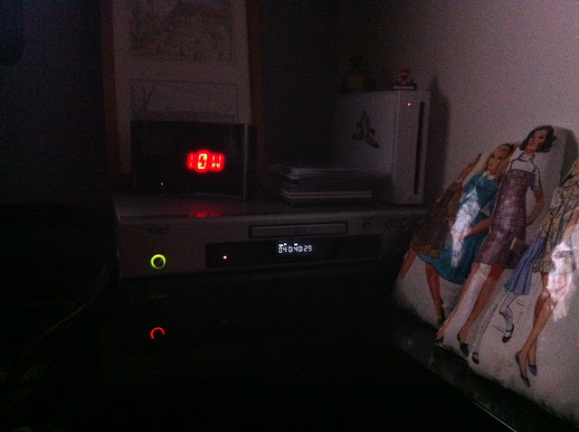
During the evening, watching a movie, I was keeping an eye on the Net Usage displayed by Wattson and these are shots attesting that we were all the time close to 0W - or not far by few Watts -


Update April 30th 2013:
Last night I did some more testing and modifications in the software - ESC output adjustments - and from 10PM to 12PM the ESS delivered power much closer to the house usage than the two hours before, as you can see on the power graph below

Saturday, I received my last order: an RC ESC : Electronic Speed Controller for Radio Controlled models
I had this idea from the beginning of my project and wanted to use one of those to deliver the exact amount of power to the DC - input- side of a big -several thousands of Watts - Grid Tie Inverter ; But I gave up the idea because this contoller would have to be able to deal with pretty big current : 100A or more and a big GTI is pricy too, and running it at low power could cause it to be very inefficient ...
But lately this idea came back to me, and this time, I thought: Why not use an ESC on one of the GTIs only, this way this GTI's output would vary from 0W to 220W instead being 0W -OFF- or 220W -ON-, and the ESC would have to deal with only 10A of DC current from the battery pack to the GTI's input (220W / 25V = 8.8V)
So I started to look into a good quality Electronic Speed Controller and found this one right away after reading about it on a RC boat forum in France, somebody was looking for a 24V "beefy" ESC and somebody advised this one right away, saying it was a quality product, that would do the job with no over heating problem ... After a little email exchange with the British maker of those I got the strongest one that can do 40A and is forward only -which is exactly what I need here -
So this is an important step stone of my DIY ESS project here and it took place yesterday, pretty much all day ...
Royal Mail package received from the UK

and here is the nice Electronize ESC

After trying to test it with a potentiometer and realizing that it would not work, and had to digg out and old RC boat and used the remote control to test the Controller

using the receiver unplugging the boat ESC, and plugging in the new ESC

testing with a 12V AGM battery first, a voltmeter and a DC motor

I found the Neutral point using the remote trim, and reading 12.55V on the voltmeter

now pushing the lever forward or backwards the voltage climbed to 13.25 which was the battery's voltage

After this first test, I connected the ESC to a GTI and it work fine, low power output, but fine

the GTI DC side would not even light up its red LED, but pushing the lever slowly it would get to that point and then from there, the 3 green LED would start their usual flashing sequence


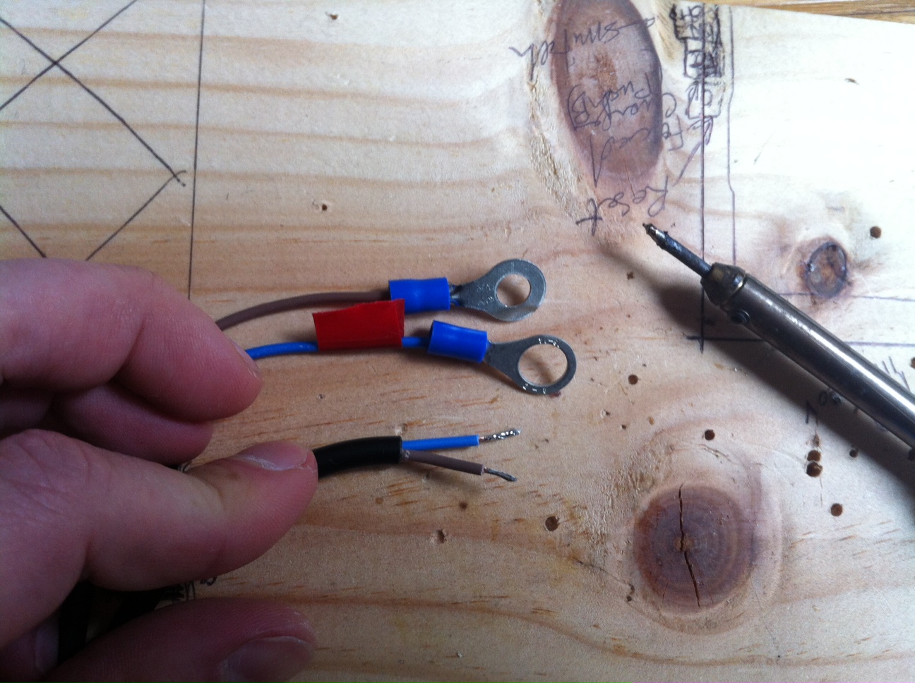
After this initial and positive testing part, I did some soldering to attach 8mm lugs to each wire

I am starting to get used to this now


After that came the ESS software update to take this new ESC into account and make it works on the GTI #1 and along with the rest of the components; After that I uploaded it to the Arduino board and left the computer plugged in to monitor the log ouput by the arduino board while the software is running

The "battery side" - input - of the ESC is now connected to the other GTIs inputs of the stack and its "motor side" - output - is connected to GTI #1

The 5V power and signal command wires are connected to a PWM pin of the Arduino board, increasing or reducing the signal's "intensity" to make the ESC deliver more or less current to the GTI #1

Close up on the hardware connections

Close up on the ESC

This was the first test of the ESS with this new setup, and it worked fine right away !! :-)

Here is a the first test video of this new setup
After a little time at the park for the kids and soem more forced charging to refill the battery pack, it was time to celebrate, Jack Rickard's style, with a good bottle of vintage whisky

During the evening, watching a movie, I was keeping an eye on the Net Usage displayed by Wattson and these are shots attesting that we were all the time close to 0W - or not far by few Watts -


Update April 30th 2013:
Last night I did some more testing and modifications in the software - ESC output adjustments - and from 10PM to 12PM the ESS delivered power much closer to the house usage than the two hours before, as you can see on the power graph below