Wiring of the main switch to the programmable dual relay voltmeter and fuse holder & fuse for the 24V command line

I dismounted a car lighter socket 24V to 5V DC-DC converter to use it to power the Arduino board through its micro USB port

Removal of the PCB from the plastic case


Welding of the positive and negative leads for 24V input

Heaving gauge red cable screwed onto the battery positive terminal

Test with the main switch on charger position : The charger is charging (good news) and almost no heat is detected on the charger relay power terminal

From the top: USB cable plugged in at both ends & Charger leads screwed to charger input on the board

Switch on inverter mode, contactor is switching to ON with a big audible "clap" ...

... and 24V to 5V DC-Dc converter is on (blue light on the left)and 24V to 5V DC-Dc converter is on (blue light), ...
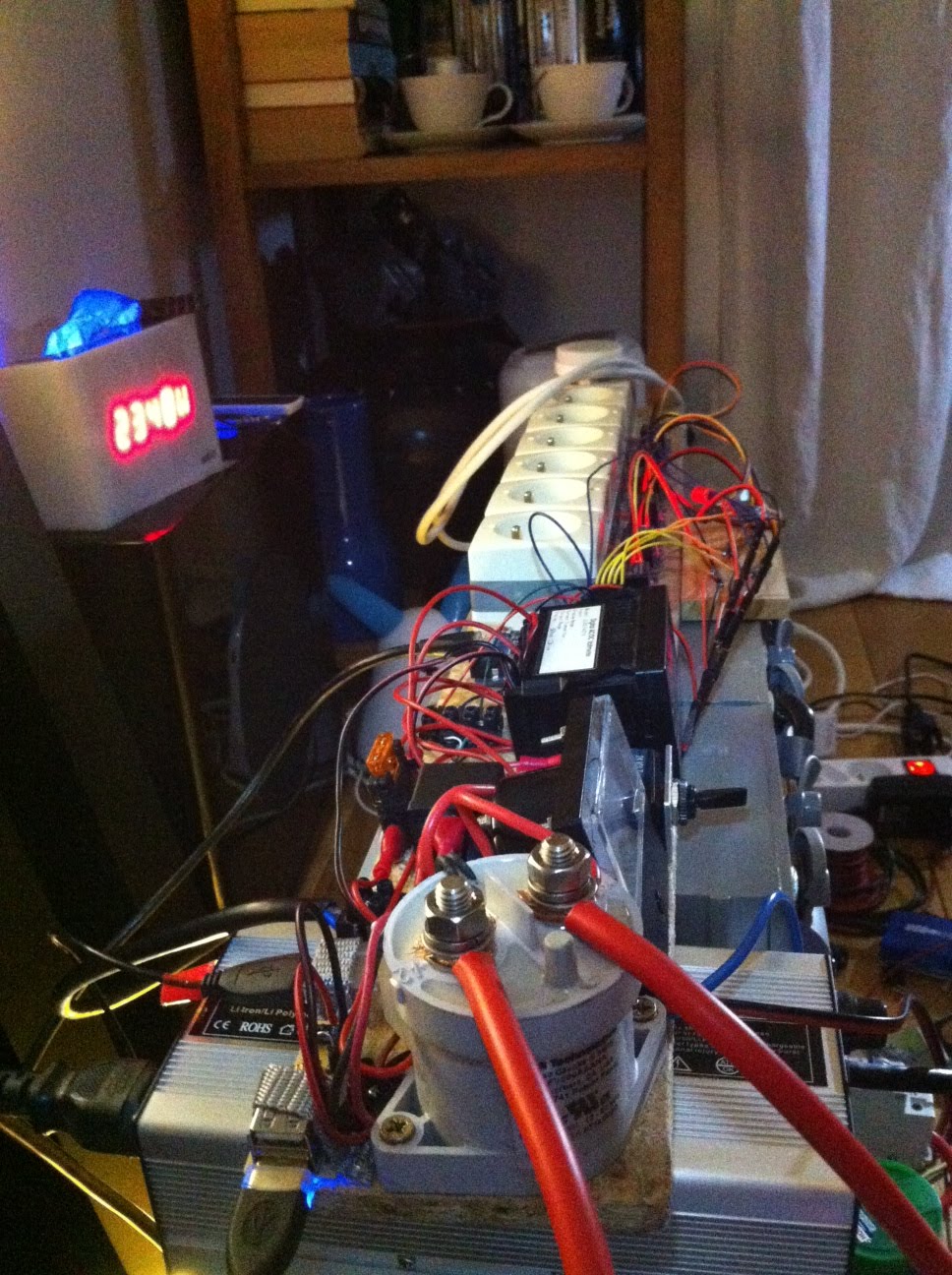
... powering the Arduino board which is starting its relay activation sequence

To be continued, but almost finished ...
No comments:
Post a Comment