Showing posts with label 24V. Show all posts

Monday, June 3, 2013

DIY ESS - 24V fan mounted in the metal cabinet & components destinations

Update on the IKEA metal cabinet :


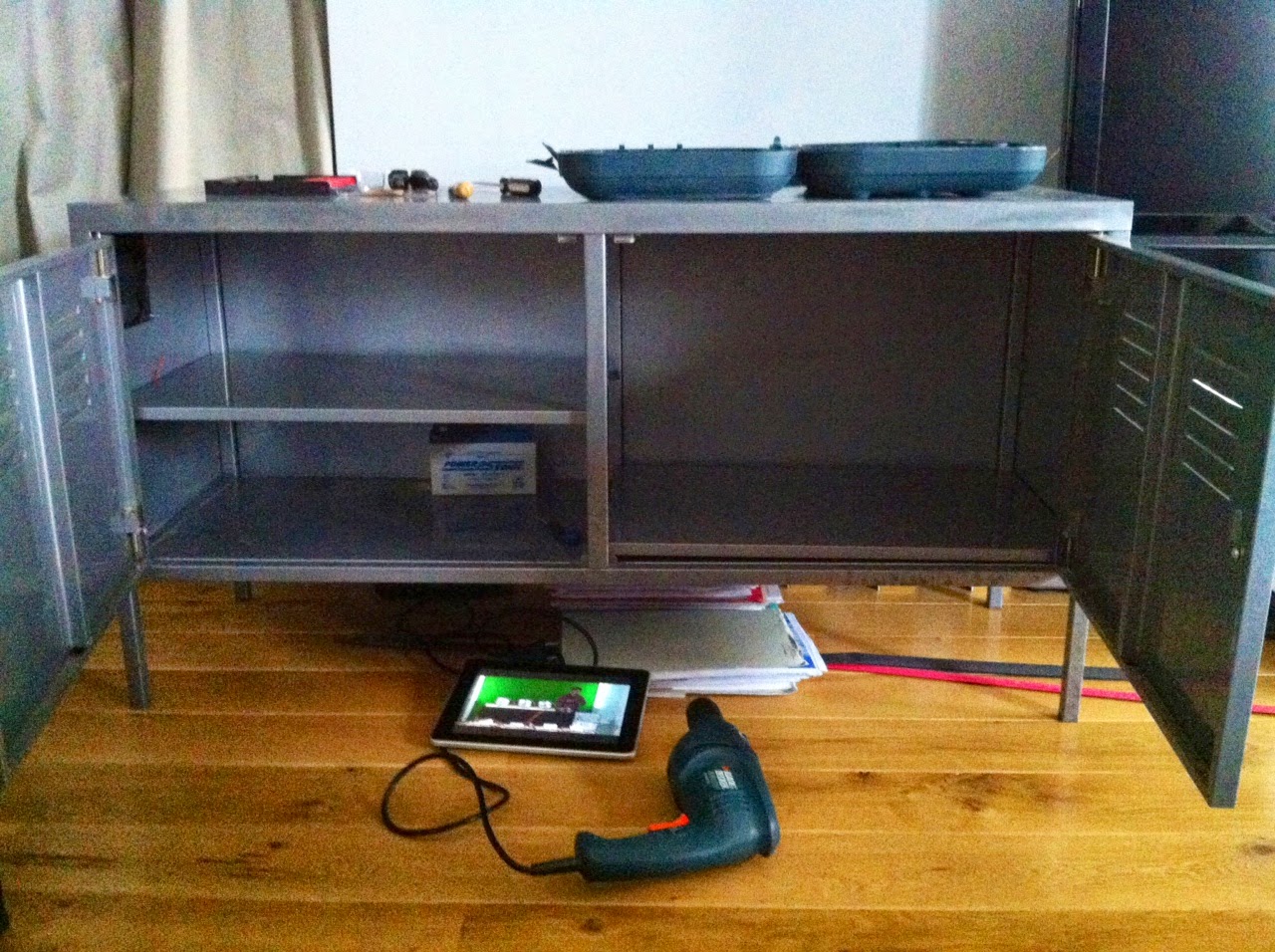
I drilled 4 holes to mount the 24V fan in the upper front left corner of the metal cabinet last night ...


 ... since the grid tie inverters should be positionned on the left upper shelf

Underneath, I will place the Control Board / EMS 

On the right, there is room for the 8 cells battery pack, and even for double, 16 cells, to upgrade to 10kWh, maybe later, if necessary ... 

Also, the right shelf is not used since the cells are 30cm high, but I found that putting it on top of the right bottom (rather thin) piece of metal will make the whole thing stronger to hold the 6*8 = 48kg of the battery pack

Tuesday, March 12, 2013

Another Tyco Kilovac Contactor and an Emergency Cut Off Pushbutton

Yesterday I got this other - brand new this time - Tyco Kilovac Contactor to replace the automotive 24V relay on the charger side of my DIY ESS. Like Jack Rickard says and uses for his heating system, it is overkill but you do not want to leave a ceramic hetaer load on that drains your battery pack to flat, for me, I do not want to chargers not to stop when the battery pack reaches the voltage limit of 3.50V per cell times 8 cells, in my case 28V


I also got, from the same eBay seller here in Paris, a small emergency cut off pushbutton/switch that will cut the 24V to the ESS box and deactivate all contactors, arduino, relays ... and hopefully stop any problem


Just realized after buying it that it is a Tyco Kilovac EV200A1ANA, and not the one I have already for the Grid Tie Inverter side, which is an EV200AAANA; The difference is that this new one I got does not have the Coil Economizer, so I guess it will use more power when the coil is activated - during the charge mode -


The 24V automotive relay, works fine, but get a bit hot, and you never know when it is going to stick/weld inside and not open when necessary, I just do not trust it as much as a good Tyco Kilovac Contactor 

Friday, February 15, 2013

Yeehaaaa ! My 8 CALB CA180FI Cells arrived this morning ! :-)

I still can not believe they are here finally ... I had been thinking and waiting to buy them

The delivery guy did bring one out of two parcels upstairs and my wife texted as I was on my way to work, so turned my Vectrix around and went back to take care of this - I did not want to leave these in the hallway of our building all day long -

She opened one of the box for me

and here they are, well packaged 

wow ! just as I expected :-)

And then off to work ...
I can not wait to get back home to measure the voltage of each cell, start wiring them up in series, etc ..

A lot of bottom balancing ahead ...

I read again and will use the precious advices of Jack Rickard from EVTV on these super cells 


Special Thanks to Anne Kloppenborg from Amsterdam ;-)

LiFePO4 ESS - La suite

First I soldered these 2 x 20 pins together to bring ground and 5V to all the relays

It looks nice & clean like this and the connections are tight


Then I worked on the 24V command part wiring: battery pack leads, fuse, voltmeter, automotive relay, Tyco Kilovac contactor, Charge Mode relay, GTI Mode relay, main switch, 24V to 5V DC-DC power supply ... 

These are the battery pack leads, with 8mm small lugs, which will be screwed directly onto the terminals

More tonight or tomorrow ...

Wednesday, October 17, 2012

LifePO4 ESS - Control Board Rebuilding Update

As of last night, this is where I ended with my BESPSS control board rebuild:

Overview of the left side of the board, the right side being the relay activated outlets

- Heavy gauge wire connecting battery pack to Kilovac contactor cut and screwed
- USB connector for Wattson USB connector (providing colors voltages)
- Charger leads input terminals, with positive connected to charger automotive relay, going through the Ampmeter, and to contactor battery positive lead; I am using solid core 2.5mm² wires here to handle the 10A coming from the charger

- A automotive fuseholder and 3A fuse are mounted vertically to save space
- The main swith is screwed to the board (was already done last time I think)
- The Arduino board is not moving
- The programmable dual relay Voltmeter is fitted between the Arduino board and the main switch 

I also ordered a 24V automotive lighter socket USB converter, that will provide 5V to the micro USB used to power the Arduino board (I had problems with the power supply using 12V); After testing it, I will probably open it and only keep the PCB connecting the battery 24V to its input and will plug the USB to micro USB cable in its USB output

Friday, October 12, 2012

LiFePO4 ESS News - 24V charger security relay and 12V power supply to Arduino board

Last week end activities on my LiFePO4 ESS (Battery Energy Storage & Power Supply System):


- Swap the 12V charger security automotive relay for the 24V (30/40A) one (received quite a while ago):

The contact is better now because this relay is just more adapted to this voltage and it is heating up a lot less than the 12V one 
Also the 12V relay used to get stuck from time to time, and being a security charger side cut off, in case the charger does not stop, it would not be of any help !


- Power the Arduino board through its power supply inlet:

I am now running the programmable dual relay voltmeter and Tyco Kilovac contactor from the 24V battery pack directly, and then used the DC-DC converter to power the Arduino board, switching it on when the ESS is in Power Supply Mode ... and it worked perfectly ...


... only in the beginning, because something strange happened: the automated power on and off of the relays activating the grid tie inverters did not seem to work well anymore after that, and it took me little time to find out why. I thought : "What's wrong, this program loaded in the Arduino board micro-controller has not changed for weeks, Wattson color voltages thresholds can not change, they did not for weeks... The only thing I changed today is this power supply: from micro-USB 5V to power inlet 12V"
I also realized that this power inlet area on the board was heating up abnormaly ... (?)
So I removed it, switched back to micro-USB 5V and everything worked like a charm , as it did for the last weeks :-)   I still do not understand what is wrong with this power supply inlet, the DC-DC converter provides exactly 12V, nothing more


Nice green (small) negative usage, the (almost) perfect situation when running in Power Supply Mode


Also received in the mail, the 4 4700uF 35V 105°C capacitors to replace the vented one in the last damaged Grid Tie Inverter

Thursday, July 5, 2012

LiFePO4 ESS update - 24V relay & Arduino board


My 12V automotive relay for the charger line is not really the right component to carry 24V @ 10A and is heating up a lot, got stuck few times, so I decided to buy a 24V one, and it arrived 


More important, following my work on getting color codes from Wattson, I ordered an received an Arduino Leonardo card and 3 high voltage relays
This board will read the voltages from green, blue, red Wattson LEDs as inputs, and using a program, trigger signals on the outputs to activate relays, switching ON & OFF my Grid Tie Inveters

Nice packaging

It is smaller than I tought

Monday, June 11, 2012

LiFePO4 Energy Storage System - New 24V configuration - 3 Remote Controlled Grid Tie Inverters

As I announced at the end of my last video, I spent this sunday changing my System to its new 24V configuration and also changed the cells layout as you can see

The New interesting feature of my Energy Storage System is these 3 Remote Controlled Grid Tie Inverters ...

Long test of the New system


Following are all the transition pictures:

Disassembling the 48V battery pack

Testing new layout

That one would use less space on the floor and still give me full access to individual cells to monitor voltage once in a while

What took a long time was polishing (with sandpaper) the cupper bars linking the cells together: they have to be exempt of oxydation to conduct current well

Each time a group of 4 cells was finished (4 cells in parallel) I would connect it to the string (8 groups in series)


Second level ...

A 100A breaker is placed at mid-pack (on the right)

Battery pack fully assembled, Tyco Kilovac contactor bolted to the positive terminal, DC-DC 24V to 12V converter and dual relay programmable voltmeter connected

Now time to install the 3 Grid Tie Inverters I had in stock from previous tests (bottom to top: SUN 250G, SUN25G, SUN 300G)

And the positive terminals of the GTIs are connected to the switched 24V from the Kilovac contactor
The lower voltage limit (cut-off) on the voltmeter has been changed from 48V to 24V
I brought Wattson to see the effect of this New Energy Storage System on my home power consumption


Overall view of the finished system, remote controlled outlets / sockets included (left)


I can now control my Power Supply to the grid with the remote while I am upstairs or doing something else


Short test after mounting everything


In the morning light

The remote control and the 3 controlled outlets / sockets

Top view

Next setp tonight: I will be adding a small relay/contactor for the charger side; My new 24V charger (10A) is on its way from China and will arrive soon hopefully ...

Please Share this Post if you Liked it !

Please Share this Post if you Liked it ! Thanks !
Related Posts Plugin for WordPress, Blogger...