Showing posts with label control board. Show all posts

Sunday, May 26, 2013

Just added the List of major Components to the LiFePO4 DIY ESS Blog and why I chose them


I chose the BEST components to create this ESS:


Energy Monitor: Created in 2006, Wattson is for me the best: it displays clearly in real time your home Usage, Production & Net usage with large visible digits and colors; Using RF, it can travel in your home since it is also battery powered; Easy to install and it looks like a design object 

LiFePO4 Batteries : CALB CA Series Cells are simply the best Li-ion Cells avaibale today: safety, stability, cycle life, power, and energy density at a reasonable price; Read Jack Rickard's article about these new amazing new cells


DC Switch & Breaker : Blue Sea 187-Series Circuit Breaker - Surface Mount 150A; A reliable marine quality high current Switch and Circuit Breaker placed in the middle of the battery pack to be able to switch off completely the whole system, and a protection in case of short circuit; Product link

Grid Tie Inverters : the SUN250G has been a very good GTI for years, is more efficient than a Power Jack (similar product); they can be used in parallel, their DC input accepts 10.8V to 30V, which is perfect for my 24V battery bank; They have a one year warranty; They are very affordable, 110-230VAC 

Chargers : LiFePO4 24V Simple Charger, Light, Low power, Low price, used in parallel, 110-230VAC 

Contactors : 2 Tyco Kilovac EV200AAANA : Simply a world reference for years, Made in the Santa Barbara, USA : Carries high current (500A) and provide a Very Reliable cut off

Mother Board : Very famous widespread programming board, the Arduino is made in Italy, with a French micro-controller chip on board, small power consumption, and has been working for the last year now with no failure

Relays : Small standalone design, with red led to indicate that it is closed/active, standard connector, low cost, have been working for the last year now with no failure; If any, each relay can be changed in 1 or 2 minutes with a small screwdriver

Controller : The ESC (Electronic Speed Controller) used is probably the best in the world, Made in the UK, micro-controller based, does not heat and can carry high current up to 40A at 26.6V which is more than we need here;Product Link

Voltmeter : This programmable dual relay digital voltmeter is  the key to monitoring the Battery pack charge and discharge limits, and keeps it in the safe range; It is available only in the USA, is easy to program manually, is precise enough and does the job !


----------------------------------------------------------


More about my LiFePO4 DIY ESS here

Monday, May 20, 2013

LiFePO4 ESS - User settings can be modified and saved in the EEPROM

Users can now change Variables in my DIY ESS program and save them in the EEPROM for the next runs; This is a major enhancement and I think it will be usefull


If necessary, the users will be able to plug their Mac or PC to the Arduino board via a regular USB cable and see the log displayed by the program


If some of the frequency, sensitivity, thresholds need to be adjusted, it can be done using a simple code letter and value:

i.e.: 'd100' + Enter will change the delay between two readings from the original 50ms to 100ms, and if this is happens to be a good value for the behaviour of his ESS, the user can save it typing 'save' + Enter

The modified value(s) will then be located in the Arduino's EEPROM (Read Only Memory) and will reside there even if the power is switched Off, for the next runs

At start up, the ESS arduino board program will read values stored in the EEPROM and use them 

Typing 'config' + Enter, the program will display all the variables stored in the EEPROM


Monday, April 29, 2013

LiFePO4 DIY ESS - New : ESC for fine GTI input Power Tuning

Good News : My LiFePO4 DIY ESS is now even more precise !

Saturday, I received my last order: an RC ESC : Electronic Speed Controller for Radio Controlled models

I had this idea from the beginning of my project and wanted to use one of those to deliver the exact amount of power to the DC - input- side of a big -several thousands of Watts - Grid Tie Inverter ; But I gave up the idea because this contoller would have to be able to deal with pretty big current : 100A or more and a big GTI is pricy too, and running it at low power could cause it to be very inefficient ...

But lately this idea came back to me, and this time, I thought: Why not use an ESC on one of the GTIs only, this way this GTI's output would vary from 0W to 220W instead being 0W -OFF- or 220W -ON-, and the ESC would have to deal with only 10A of DC current from the battery pack to the GTI's input (220W / 25V = 8.8V)

So I started to look into a good quality Electronic Speed Controller and found this one right away after reading about it on a RC boat forum in France, somebody was looking for a 24V "beefy" ESC and somebody advised this one right away, saying it was a quality product, that would do the job with no over heating problem ... After a little email exchange with the British maker of those I got the strongest one that can do 40A and is forward only -which is exactly what I need here -

So this is an important step stone of my DIY ESS project here and it took place yesterday, pretty much all day ...


Royal Mail package received from the UK

and here is the nice Electronize ESC

After trying to test it with a potentiometer and realizing that it would not work, and had to digg out and old RC boat and used the remote control to test the Controller


using the receiver unplugging the boat ESC, and plugging in the new ESC 

testing with a 12V AGM battery first, a voltmeter and a DC motor

I found the Neutral point using the remote trim, and reading 12.55V on the voltmeter

now pushing the lever forward or backwards the voltage climbed to 13.25 which was the battery's voltage

After this first test, I connected the ESC to a GTI and it work fine, low power output, but fine

the GTI DC side would not even light up its red LED, but pushing the lever slowly it would get to that point and then from there, the 3 green LED would start their usual flashing sequence


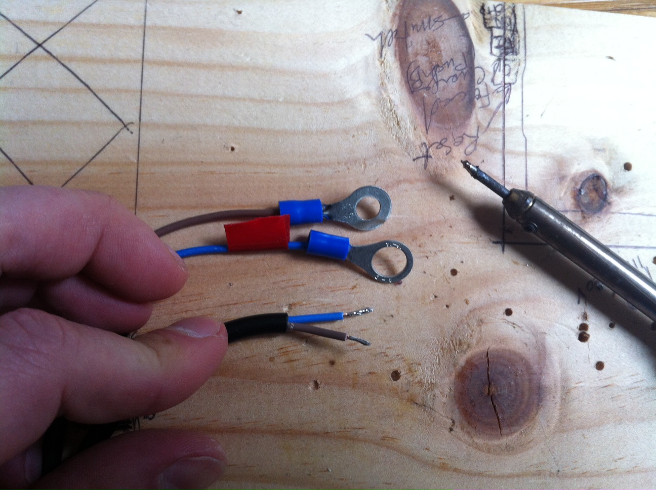
After this initial and positive testing part, I did some soldering to attach 8mm lugs to each wire

I am starting to get used to this now


After that came the ESS software update to take this new ESC into account and make it works on the GTI #1 and along with the rest of the components; After that I uploaded it to the Arduino board and left the computer plugged in to monitor the log ouput by the arduino board while the software is running

The "battery side" - input - of the ESC is now connected to the other GTIs inputs of the stack and its "motor side" - output - is connected to GTI #1

The 5V power and signal command wires are connected to a PWM pin of the Arduino board, increasing or reducing the signal's "intensity" to make the ESC deliver more or less current to the GTI #1 

Close up on the hardware connections

Close up on the ESC

This was the first test of the ESS with this new setup, and it worked fine right away !! :-)

Here is a the first test video of this new setup


After a little time at the park for the kids and soem more forced charging to refill the battery pack, it was time  to celebrate, Jack Rickard's style, with a good bottle of vintage whisky


During the evening, watching a movie, I was keeping an eye on the Net Usage displayed by Wattson and these are shots attesting that we were all the time close to 0W - or not far by few Watts -


Update April 30th 2013:

Last night I did some more testing and modifications in the software - ESC output adjustments - and from 10PM to 12PM the ESS delivered power much closer to the house usage than the two hours before, as you can see on the power graph below


LiFePO4 DIY ESS - Charger Stuff

If you remember the last time I got 3 24V LiFePO4 Chargers, one of them did not blow any air and went into an over-temperature situation; I had my Hong Kong contact send me another one and it arrived last night


The new charger is exactly like the six others, except this blue sticker instead of orange


Only now I decided to open the problem charger, and discovered that its fan connector was simply not plugged into the charger PCB ... This was easy to fix ! :-)


I then replugged it the the ESS Control Board / EMS to test it and the fan started spinning right away :-) 


Now, let's prepare this new charger to connect it with the other ones: 
Always the same thing: remove the original US AC plug, strip the wires and apply solder to make it stronger; On the DC side, remove the plug, strip the wires and solder 8mm lug on positive and 6mm lug for negative 


Done !


So I now have 7 Low Power Chargers to feed my battery pack, and had to plug 2 on the same AC port, together pushing 650W

The stack is getting a bit high with 7 chargers !

2 chargers are connected to the same AC port

7 x 92W = 650W (roughly)

It is tight, but all the DC chargers cables fit

This is the new charger positive lug

and the negative one


Please Share this Post if you Liked it !

Please Share this Post if you Liked it ! Thanks !
Related Posts Plugin for WordPress, Blogger...