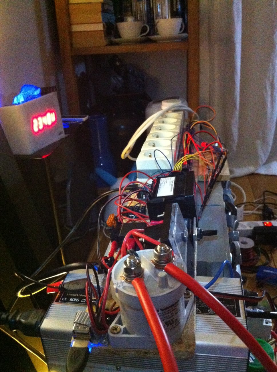
5 Arduino Leonardo boards have arrived from Evola.fr website faster than I thought and one of them is already flashed with the DIY ESS program, from the Mac this time

Showing posts with label micro USB. Show all posts
Tuesday, July 30, 2013
DIY ESS - First 5 Arduino Leonardo boards received - First one flashed & ready to ship
Libellés :
arduino,
Atmel,
board,
chip,
compile,
DIY ESS Kit,
EEPROM,
flash,
flashed,
for sale,
kit #1,
micro processor,
micro USB,
pcb,
processor,
program,
ROM,
sell,
usb,
USB port
Tuesday, February 12, 2013
LiFePO4 ESS - Enclosure found
Last night, after a long shopping, I think I found a good technical enclosure at Muji's; It is a drawer, made of sturdy transparent plastic - this way I can see all the components inside lighting up -, and I will use it to cover the board by screwing it from the sides into the wooden board
Not too high
This wooden board in not wide enough now, I will have to get another one, and anyways it would have too packed and not scalable for more grid tie inverters/ chargers and maybe a bigger Arduino board like the Mega
Also found some real AC breakers
Not too high
This wooden board in not wide enough now, I will have to get another one, and anyways it would have too packed and not scalable for more grid tie inverters/ chargers and maybe a bigger Arduino board like the Mega
Also found some real AC breakers
Now I just came back from a Leroy Merlin - our French Home Depot - with a 1cm thick wooden board cut at the exact dimensions of the plastic cover ...
Libellés :
AC breaker,
BESS,
box,
breaker,
cable,
circuit breaker,
DIY ESS,
DIY ESS Kit,
enclosure,
energy storage,
ESS,
micro USB,
pin,
power supply,
relay,
wood
Friday, October 19, 2012
LifePO4 ESS - Control Board Rebuilding Update #3
After testing the charge mode for almost 3 hours, eveything is fine (relay heating up a little but nothing abnormal, no heating at all on the wires), so I am charging the whole day today


All 6 grid tie inverters have been plugged in the relay activated outlets
To spread the battery power, each grid tie inverter DC side is connected to its neighbor with a 2.5mm² solid core cupper wire and I may need to double it for the first ones
Also an heavy gauge black cable has been connected from the negative battery pack terminal to the negative DC terminal of the grid tie inverter in the middle of the stack
Testing the inverter mode: I thought everything was going fine, until being under 0W, pushing power outside my home grid, Wattson glowing green and showing - 150W, the grid tie inverters should start to shut off one after the other; But here, nothing for several minutes !? Something was wrong ...
I thought the Blue/Red/Green signal coming from Wattson was affected by the proximity of other live wires and started to move the voltmeter, etc... but nothing changed
It made me think of my Arduino power supply problem 2 weeks ago: Supplying 12V from the battery pack through a ebike.ca 72V to 12V DC-DC converter, I had the same problem
Here I was using a 12V/24V to 5V DC-DC converter (from a car lighter socket USB converter) to power the Arduino board and it looks like it was the source of my problem:
I then disconnected the USB cable from this USB DC-DC converter, and used the 220V USB hub power supply instead, and everything was back to normal ! Interesting ...
Conclusion: It looks like the Arduino board does not like any DC-DC converter with the battery pack as a power source !
Libellés :
BESPSS,
BESS,
dc-dc,
dc-dc converter,
DIY ESS,
ESS,
LiFePO4,
live wire,
micro USB,
relay,
usb,
voltage,
wattson
Thursday, October 18, 2012
LifePO4 ESS - Control Board Rebuilding Update #2
Wiring of the main switch to the programmable dual relay voltmeter and fuse holder & fuse for the 24V command line
I dismounted a car lighter socket 24V to 5V DC-DC converter to use it to power the Arduino board through its micro USB port
Removal of the PCB from the plastic case
Welding of the positive and negative leads for 24V input
Heaving gauge red cable screwed onto the battery positive terminal
Test with the main switch on charger position : The charger is charging (good news) and almost no heat is detected on the charger relay power terminal
From the top: USB cable plugged in at both ends & Charger leads screwed to charger input on the board
Switch on inverter mode, contactor is switching to ON with a big audible "clap" ...
... and 24V to 5V DC-Dc converter is on (blue light on the left)and 24V to 5V DC-Dc converter is on (blue light), ...
... powering the Arduino board which is starting its relay activation sequence
To be continued, but almost finished ...
Libellés :
arduino,
battery,
battery bank,
BESPSS,
BESS,
contactor,
control board,
DIY ESS,
ESS,
LiFePO4,
micro USB,
relay,
usb
Friday, October 12, 2012
LiFePO4 ESS News - 24V charger security relay and 12V power supply to Arduino board
Last week end activities on my LiFePO4 ESS (Battery Energy Storage & Power Supply System):
- Swap the 12V charger security automotive relay for the 24V (30/40A) one (received quite a while ago):
The contact is better now because this relay is just more adapted to this voltage and it is heating up a lot less than the 12V one
Also the 12V relay used to get stuck from time to time, and being a security charger side cut off, in case the charger does not stop, it would not be of any help !
- Power the Arduino board through its power supply inlet:
I am now running the programmable dual relay voltmeter and Tyco Kilovac contactor from the 24V battery pack directly, and then used the DC-DC converter to power the Arduino board, switching it on when the ESS is in Power Supply Mode ... and it worked perfectly ...
... only in the beginning, because something strange happened: the automated power on and off of the relays activating the grid tie inverters did not seem to work well anymore after that, and it took me little time to find out why. I thought : "What's wrong, this program loaded in the Arduino board micro-controller has not changed for weeks, Wattson color voltages thresholds can not change, they did not for weeks... The only thing I changed today is this power supply: from micro-USB 5V to power inlet 12V"
I also realized that this power inlet area on the board was heating up abnormaly ... (?)
So I removed it, switched back to micro-USB 5V and everything worked like a charm , as it did for the last weeks :-) I still do not understand what is wrong with this power supply inlet, the DC-DC converter provides exactly 12V, nothing more
Nice green (small) negative usage, the (almost) perfect situation when running in Power Supply Mode
Also received in the mail, the 4 4700uF 35V 105°C capacitors to replace the vented one in the last damaged Grid Tie Inverter
Libellés :
12V,
24V,
35V,
4700uF,
battery,
battery bank,
BESPSS,
BESS,
capacitor,
DIY ESS,
ESS,
grid tie inverter,
LiFePO4,
micro USB,
power supply
Subscribe to:
Posts (Atom)
Please Share this Post if you Liked it !
Please Share this Post if you Liked it ! Thanks !